Creating and Simulating LEO Constellations with Skydel
Tutorial
GSG-8 is the latest positioning, navigation, and timing (PNTPosition, Navigation, and Timing: PNT and map data combine to create the GPS service.) test solution offered through Orolia’s GSGA GNSS Signal Generator is a device that is able to create simulated satellite signals and generate real RF signals by first producing I/Q data and calculating the orbits of satellites at a user-defined time, location and trajectory. family of simulators, powered by the Skydel Simulation Engine. It was developed to deliver the highest standard of Global Navigation Satellite System (GNSSGlobal navigation satellite system (GNSS): A general term describing any satellite constellation that provides positioning, navigation, and timing (PNT) services on a global or regional basis. See also) signal testing and sensor simulation performance in an easy to use, upgradable, and scalable platform.
This document explains how to configure and generate signals from a LEOLEO - Low Earth Orbit. LEO refers to the orbit that most artificial satellites travel within. LEO is closer to earth compared to other satellite constellations such as GPS and GEO satellite systems. LEO is approximately 1,200 miles above Earth or less, meaning the satellites in this orbit travel at high speeds (i.e. 15,000 mph) and can orbit the Earth in less than 2 hours. Most human spaceflight missions have ocurred within LEO. constellation with Skydel, running on a GSG-8 or other supported hardware configurations.
Introduction
Low Earth Orbit is the orbit around earth with an altitude above Earth’s surface between 250 kilometers and 2,000 kilometers (1,200 miles) and an orbital period between 84 and 127 minutes.

The goal of this document is to give some guidance to the Skydel user who aims to create a LEO satellite constellation. In this Application Note, we show two ways to do this:
- Using the Skydel Advanced Jamming feature
- Using the Galileo constellation
In the first method, we use the Advanced Jamming tool to create several moving transmitters which constitute our LEO satellites. We also use the IQ Replay feature available in Skydel to Replay a GNSS signal generated.
In the second case, we modify the Keplerian parameters of the Galileo satellites to transform them into LEO satellites.
For the first test, the customer must have the feature SKY-ADVJAM activated in their license to perform this simulation.
The goal is to create a LEO constellation that would be about 1000 km altitude, which corresponds to a root semi-major axis of 2716.3 m1/2 (LEO 1000 km altitude).
In geometry, the major axis of an ellipse is its longest diameter: a line segment that runs through the center and both foci, with ends at the two most widely separated points of the perimeter. The semi-major axis (major semi-axis) is the longest semi-diameter or one half of the major axis, and thus runs from the center, through a focus, and to the perimeter. The semi-minor axis (minor semi-axis) of an ellipse or hyperbola is a line segment that is at right angles with the semi-major axis and has one end at the center of the conic section. For the special case of a circle, the lengths of the semi-axes are both equal to the radius of the circle.

1. Create a LEO constellation using the Advanced Jamming feature
1.1. Generate LEO Satellite trajectory
In this part, we create orbital LEO trajectories and save them for use as trajectories of our LEO constellation that we want to create.
The steps we use here to create the LEO satellites are:
- Generate the trajectory of each LEO satellite.
- Generate IQ signals from each LEO satellite.
- Create a configuration and import the trajectories and IQ signals to create our LEO constellation.

We use Skydel to generate our trajectory and our LEO signal. The user can also get their trajectory and the IQ files from an external system and then import these elements into Skydel.
The required license features are SKY-ADVJAM and SKY-IQFILE.
1.1.1. Start Skydel and Create a New Configuration
To launch Skydel on a Linux system, simply type Skydel-SDX in the terminal. In Windows, locate Skydel in the start menu and click on it.
Click Continue, and then select New Configuration.
To add a output, navigate to Settings – Output.

Select the None and click the Add button.

Click on Edit in the Radio setting to set your radio configuration.

Click on Signal selection Edit to select your signal and choose GPSGlobal Positioning System is a navigation satellite system. See also L1 CA.

1.1.4. Set Vehicle Trajectory
a. Create the trajectory of the LEO satellite 1
We create the orbital trajectory of our first LEO satellite using the Earth-Orbiting Spacecraft.
Go to Settings –> Vehicle –> Body to set your LEO satellite trajectory.
Select Earth-Orbiting Spacecraft and click on Edit.

We use the Keplerian Parameters to set the trajectory of each LEO satellite.

Then go to the Settings –> Global menu and check the Raw Logging.

We now record a 10 minute trajectory. To set this duration, go to the Settings –> Global –> Start Time menu and select 10 min for the duration.

Start the simulation by clicking on the Skydel start button. At the end of the simulation, go to the Skydel-SDX/Output/your configuration and rename receiver_antenna.csv file to receiver_antenna_1.csv. Then copy and paste the file in your work folder.
b. Create the trajectory of the LEO satellite 2
In this part, we just change the orbital trajectory of our setup to generate a second orbital trajectory for our second LEO SatelliteShort for Low Earth Orbit satellite; typically an electronic device or equipment which orbits between 200 and 2,000 kilometers above the earth. Circles at a lower altitude than geosynchronous satellites..

Start the simulation by clicking on the Skydel start button. At the end of the simulation, go to the Skydel-SDX \ Output \ your configuration and save the receiver_antenna.csv file under receiver_antenna_2.csv.
c. Create the trajectory of the LEO satellite 3
We redo the same scenario as Section 1.4.2 to have the trajectory of the third LEO satellite.

Start the simulation by clicking on the Skydel start button. At the end of the simulation, go to the Skydel-SDX \ Output \ your configuration and save the receiver_antenna.csv file under receiver_antenna_3.csv.
d. Create the trajectory of the LEO satellite 4
See section 1.4.2 and set the following Keplerian Parameters as the trajectory:

Start the simulation by clicking on the Skydel start button. At the end of the simulation, go to the Skydel-SDX \ Output \ your configuration and save the receiver_antenna.csv file under receiver_antenna_4.csv.
1.2. Generate IQ signal
In this section, we show how we used Skydel to create signals that will be emitted by our LEO satellites from IQ files.
Go to Setting –> Output and select File.

Select GPS L1 C/A at 25 Msps.

Name your IQ file.

Then go to Setting –> GPS –> Signal Enable/Disable, deselect all the satellites, and select only one satellite as shown in the picture below.

Go to General and uncheck Signal Propagation Delay.

Go to Settings –> Vehicle –> Antenna and set L1 antenna to None:

Go to Settings –> GPS –> Message Modification –> LNAV and set all bit to zero to remove all navigation message.

Click on Add and Close.
Run your simulation for about 30s. Save you IQ file, and open the .xml file associated to it.
For this experiment, we have chosen a frequency of 2 GHz. This action will change the transmission frequency of the IQ signal to set it at 2 GHz.
Change the central frequency for 2 GHz:

1.3. Main configuration
1.3.1. Add an output and select your signals
To add a output, navigate to Settings –> Output and select the DTA-2115B in the dropdown list if you have a GSG-8, or select NoneRT if not.
Click on Signal Selection –> Edit to select your signal and choose GPS L1 CA.

Click a second time on Add to add another output for the interference:


1.3.2. Set Vehicle Position
Next, we configure our vehicle on a circular position. Go to Settings –> Vehicle –> Body to set your vehicle position.
For this use case we use the default Skydel fixed position:

1.3.3. Create your Leo satellite as a dynamic transmitter
The next step now is to add some transmitter that will be our LEO satellites. First, click on the Settings –> Interference submenu.

Click on Add Dynamic… and the Add Transmitter dialog box will appear.

Click a fourth time on Add Dynamic… to have four satellite. This is the minimum number of satellites allowing positioning.
Each time you add a transmitter, a new submenu with the name of the transmitter appears in the Interference submenu. We now have four transmitters in this menu interference.

a. Leo Sat orbital trajectory
To configure the transmitter, click on the “Leo Sat 1” submenu and the Dynamic Transmitter submenu will appear.
Then go in the General screen and reduce the Reference Power to 30 dBm.

Click the Trajectory button to display the transmitter trajectory page screen. Select Track as a trajectory and click on Import CSV with timestamps:

Click on Select File.

Select your receiver receiver_antenna_1.csv. Enter the position, altitude, and time.


You can ignore the following error messages:


The window of your trajectory will appear:

You can click on Close. Check Smooth/Interpolate trajectory to be able to apply a cubic spline interpolation which improves the trajectory.

Do the same for the other LEO satellites.
b. Leo Sat signal definition
Go to the Signal menu to set the signal sent by the LEO 1 satellite.

Select IQ File from the drop-down list.

In the window that appears, select the path of the IQ file to be generated.
Don’t forget to use a different name for each IQ file generated.
Click on Add and Close:

Do the same for the other LEO satellites and don’t forget to use a different name for each IQ file generated.
We then know how to connect a Ublox receiver to observe the value of the pseudo-range of the receiver. We will then look at the Ublox-RXM message from the Ublox.
We then know how to connect a Ublox receiver to observe the value of the pseudo range of the receiver.

2. Create a LEO constellation by turning GNSS Orbit into Leo Orbit
In this example, we are going to create our LEO satellite using the Galileo constellation in Skydel.
We use the Galileo constellation because the interval of the root semi major axis is between 2524 m1/2 and 8192 m1/2, which corresponds to (in meters). Leo satellites are well supported in this range. The GPS does not match because the Range interval does not match. Beidou can be used.

Therefore it covers the altitude interval of LEO satellites which is 2716.3 (LEO 1000 km altitude).
In Skydel, there are two ways in which to create the LEO constellation for this use case:
1. Import your RINEX file to fix the LEO satellite Orbit:
You can do this in Settings –> GALILEO –> General. Click on RINEX Navigation Message to import your Rinex file.

2. Modified orbital parameters using the orbits interface in Skydel:
Go to the menu Settings –> GALILEO –> Orbits for this. The modified orbital parameters must be within the MIN-MAX range.
In this example, we are going to modify the orbital parameters to create our LEO constellation using the Galileo constellation satellites.
Add a Radio
NOTE: This step is only necessary to add additional radios; a first radio will be preconfigured on your default configuration. Multiple setup options are possible; refer to the main Skydel manual for more information.
To add a radio, navigate to Settings –> Output.

Select the DTA-2115B in the dropdown list and click the Add button twice.

The DTA-2115B will be added with a default device number 0 and default clock settings. If the default values are incorrect for your hardware setup, click Edit to make the necessary changes, and click OK when done.

Select GNSS Signals
Click the Edit button for the RF A output of Radio 1 and select GALILEO E1.

Click Ok to close the Signal Selection dialog box. The output configuration should look like this:

We will now set a start date for our simulation. To do this, go to Settings –> Start Time and click on Custom Time. Set start time at the beginning of the week (ex. 29-03-2020 0:0:0).

Go to Settings –> Vehicle –> Body and set the trajectory to fixed (Latitude = 0, Longitude = 0, Altitude = 2 m ):

Go to the Skydel menu Setting –> GALILEO –> Orbits for each satellite from SV ID 1 to SV ID 4:


Go to Settings –> GALILEO –> Antenna and force the receiver antenna pattern to None:

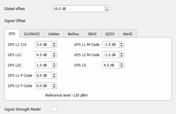
Go to Settings –> Global –> Signal level and disable the signal strength model.
The Signal Strength Model adjusts the transmit power of each satellite by modeling the following effects:
- Power loss due to the distance between the satellite and the receiver
- Power loss due to the antenna pattern of the satellite itself
Set Global Offset to 10 dB:
Go to Settings –> Global –> Atmosphere and set IONO-Delay to None.

The last step is to be able to add a LEO signal which will be sent for all the satellites. To do this, we use the Custom Signal feature.
The last step is to be able to add a LEO signal which will be sent to all the satellites. To do this, we use the Custom signal feature. This feature allows the user to create Non-GNSS signals and simulate them in Skydel. Because in most cases, Leo signals are custom signals, it varies according to the fields of application.
Click on Start to start your simulation:

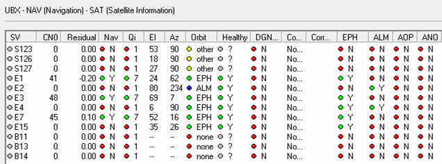
We then connected a Ublox to observe the tracked satellites. As in the previous section, we connect a Ublox receiver to our simulation’s RF output to observe the RXM message’s description. We notice that our LEO satellites are well tracked by the receiver and the information transmitted by these satellites, such as the doppler values visible and coherent.

In both configurations, be aware that you can add as many satellites as you want.
Conclusion
Skydel is a powerful tool for simulating most satellite communication scenarios. In this technical note, we first showed how to use the Advanced Jamming tool to create several mobile transmitters and constitute a constellation of LEO satellites with these transmitters. We also use the IQ Replay function available in Skydel to replay a GNSS signal.
In a second case, we showed how to modify the Keplerian parameters of the Galileo satellites to constitute a constellation of LEO satellites.
By comparing the two methods, we can see that it is easier to implement the positions of the LEO satellites with the second method because it is only necessary to change mainly the root semi-major axis value. But, the signals are more challenging to implement because, in this case, we have to create them with the custom signal option, whereas in the second case, we can use the IQ signals that we want to transmit with the LEO satellites.